 |
Home Intro Technical History Crew Models Gallery Kriegsmarine Archives More Forum
 UPDATES UPDATES |
Considerations for Calculations of Heavy Armor for Ships
The following document is one of 18 reports that were presented at a 1943 symposium on armor and projectile development that was held in Berlin. The papers that accompanied the presentation were subsequently published in a secret issue of the journal Bericht 166 der Lilienthal-Gesellschaft, with the British obtaining a copy in the immediate post-WWII period. Bericht 166 was placed in the British Ministry of Supply files under the reference GDC 10/611 from TPA 3/T.I.B.. We are currently seeking the remainder of these documents because they provide a far greater degree of insight into ongoing German R&D in the field of armor and projectile developments than has been the case in many documents we have reviewed. Any help you can provide in securing this report would help further numerous research efforts in countless ways.
The Document translated below is entitled:
Heavy Armor Plates for Warships (Die Berechnung Schwerer Schiffspanzer). Hoyer, B. (1943). OBERKOMMANDO DER KRIEGSMARINE BERLIN (GERMANY): Berlin. Germany.
We are very thankful to Ulrich Rudofsky for translating this document, which he did with his usual competence and clarity. The document’s literal title is bit deceptive because it relates far more to designing methods for calculating armor penetration than it does with the actual layout of naval armor systems. We invite the interested reader to take note of the following elements within the text that may be of interest:
1. The Germans were acutely aware of the immune zone concept and how to manipulate it to good effect. In fact, most of the article is devoted to means of calculating the inner and outer IZ, both with regards to shells that barely fail to penetrate, and those that penetrate intact. The effects of ejected plugs and discs are seen as much less important than the effects caused by the penetration of intact shells.
2. Mention is made several times the past and ongoing R & D on various pre-war armor schemes and shell experiments, and this correlates well with what was presented in ADM 213/951. To date, every primary source document we have studied on German between-war naval R&D reveals very active programs, and reference is made to experiments that could further our understanding on a number of subjects.
3. A brief review is made to various foreign armoring schemes, including the “All or Nothing” system. Apparently, the author found this system “primitive” but not without some advantages. A similar review is made of projectile development, although here the many material and technical variables involved militate against any absolute views being presented.
4. It is noted that a series of experiments were done at various obliquities to improve the performance of German shells at incidence of impact greater that 30ş. This research stands in very stark contrast to claims that no such testing was done by the “reactionary and conservative” German naval R&D community. Indeed, an entire section of the paper deals with these obliquity effects, although we need more details of the experiments that were conducted – which may be found in other papers in this series.
5. Mention is twice made of decapping principles. In one case, we see this reference applied to an initial layer of non-cemented armor that is useful in facilitating a shell’s subsequent destruction via contact with an inner layer of tempered armor. This correlates very well with experiments mentioned in ADM 213/951, and indicates that the Germans and Italians were very much on the same track with regard to decapping in the early 1930s. In another reference, it is noted that the external layer’s decapping ability will result in a loss of shell mass, although this is dismissed from the rather quick and dirty formulaic approach that is taken toward deriving IZ charts.
6. With regards to the outer armor layer used aboard German heavy ships, the author notes post-penetration shell velocity effects very prominently in at least one section of the report. Once again, this correlates very well with sections of ADM 213/951. Equal attention is given to the energy required to defeat the external layer, and this invites us to examine the energy dynamics that the Germans were considering in much greater depth. The velocity issue may relate to fuzing concerns, but this is not explicitly stated. But the energy loss issue is a critical factor to consider in a shell’s subsequent performance against the inner layer of the system.
7. Nothing is done with regard to working yaw and trajectory changes into the algorithms that are used to develop the penetration curves. This is in marked contrast to some of the material presented in ADM 213/951, which dwells on these subjects. The author notes that some may take exception with his dismissal of decapping effects, etc., in his calculations, but he maintains that the advantages in practical applications outweigh these nuances – at least based on his body of literature.
8. The feedback at the end is interesting. The two competing means of addressing penetration are presented as a detailed examination of the theoretical underpinnings of shell/armor penetration dynamics and the use empirical formulae that are largely based on actual testing. Each has certain advantages, and it is clear that this conference must have been a lively affair between the theoretical and practical application devotees. In this respect, Hoyer is very much in the practical camp – and perhaps at the extreme end of that group.
There are many other tidbits one will glean from this document, so let us now cut to the chase.
George H. Elder.
In the course of the past few days, a great many formulas were presented to you in several lectures that claimed to solve the problems of armor penetration on purely theoretical grounds, and even by the employing exacting principles of physics. However, a closer look at this will reveal that all these formulas somehow always contain a hidden empirical factor that was derived from some sort of ballistic experiment. Furthermore, one notices that these formulas are imbued with certain limitations by their creators. For example, we are asked to accept that the projectile has no armor piercing cap and that its entire manufacture conforms exactly to the projectile’s idealized type, from which a certain empirical factor was spun off. Moreover, only homogeneous material is always and explicitly assumed for armor plate [calculations]. But the terrible enemy does concern himself with these limitations, and even we ourselves use homogeneous and hardened armor materials side by side, as well as projectiles of most diverse types. In order to apply the presented formulas to practical problems, new tests are indispensable to determine other empirical factors, and experimentation, again, will have the final word.
Therefore, for problems of armor penetration, the Navy has always given preference to testing, namely, tests on the actual original [materials or ships]. You are probably asking yourself why the subject of this contribution is, “The calculation of heavy armor for ships”, and I must admit that this title is not quite correct. The inherent meaning is much more closely related to formulating a computational method that will take the earlier experimental data obtained at the firing ranges, etc., and applying these results to the problems of today. Firing data that were collected in many years of work at the firing ranges are systematically analyzed in order to apply these results in the present task.
What sort of task this encompasses has already been briefly mentioned in the introduction by Captain Meusemann. This primarily involves a problem of two ships engaged in a battle, and the determination of the most advantageous distance, i.e., the most advantageous range in which one’s own ship is relatively well protected, but at which there is an expectation that a decisive hit could be scored on the enemy. In other words, the tactical foundation for the conduct [behavior] of the ships in battle is to be established. However, the reverse case can occur when tactical considerations take precedence over the implications indicated by actual technical data. The underlying question most often concerns how much weight is available for armor in a ship of a certain weight, after subtraction of the weights taken up by the propulsion equipment (i.e., speed) and the artillery, in particular the turrets, in order to determine the optimal distribution of the horizontal and vertical armor. I will get to the basic concepts of “Horizontal and Vertical Armor” later, as well as the various parameters of armor design options.
The previously mentioned range in which one’s own ship is not in danger, is the so-called zone of protection that is formed by the so-called zones of penetration, and these are determined by the upper and lower penetration zone.
Lower penetration zone: Penetration up to E [distance] = . . . hm
Upper penetration zone: Penetration above E [distance] = . . . hm
Fig. 1: Zones of Penetration.
The sketch shows the cross-section of the main frame of a heavily armored ship. As a typical armor arrangement, the usual distribution of German ships with vertical protection and a [supporting] armored deck scarp [slope] was chosen. The two arrows indicate the preferred aims of fire within the upper and lower zones of penetration. These two concepts can be best understood in the following way. The opponent that fires at the ship with a heavy flat trajectory gun at very close range would relatively easily penetrate the lateral protection, i.e., the heavy vertical plate in the sketch, since he has at his disposal a very high terminal velocity and a very advantageous impact angle. By increasing the distance, however, the terminal velocity decreases and the angle of fall increases, i.e., the prerequisites for a penetration become less likely, until, finally, no penetration will occur after crossing a certain limiting distance. The distance from 0 to the limiting borderline distance is called the “lower penetration zone”. By increasing the distance of the gun to the target even farther, nothing else occurs for a time. The side-protection is hit with even more disadvantageous angles and, therefore, becomes impenetrable. Hits upon the horizontal protection are still ineffective since the angle of fall and, therefore, the angle of impact are still too small. By further increases in distance, the moment approaches when the horizontal protection is penetrated as a result of the steadily increasing magnitude of the impact angle. One can derive the upper penetration zone from this distance to the maximal distance of the gun’s absolute range.
Before I discuss the actual method of computation, I have to make several comments about the various factors that have an influence on armor penetration (Fig. 2). Simply stated [these are the variables]: the velocity at the target [impact velocity], the true [real] angle of impact, the characteristics of the armor, and the characteristic of the shell. Although the mention and consideration of these 4 factors may seem simply self-evident, I must, however, point out that only the impact velocity on the target [Vz] and the impact angle need to be taken into consideration in all armor penetration formulas. The actual characteristics of the armor material are still considered in only a very few advanced formulas; while the quality of the shell and its construction no longer appears in any formula. You will see in my subsequent demonstrations how particularly important the consideration of these factors is.
Vz = Impact velocity.
Vo = Muzzle velocity.
ω = Angle of fall of the projectile.
ψ = Relative position angle of ship.
χ = Angle of heel or roll.
ϑ = Angle of inclination of the armor belt.
“i-value” = [I believe this is a trajectory function defined by, amongst other variables, air resistance (a function the shell’s cross-sectional area), initial velocity, shell mass, and shell form. GHE]
Figure 2. Factors that affect armor penetration.
Now let us discuss a few individual facts about each of these factors. The final velocity of the projectile, i.e., the Vz (striking velocity at the target), at a given distance is ascertained from the firing table. Naturally, the assumption is that this pertains to one’s own gun and one’s own ammunition for which a firing table is available. Calculating the chances of the opponent achieving penetration against our own ship is obviously a more difficult problem. At best, the opposing gun’s Vo [muzzle velocity], shell weight, and shell’s approximate external measurements are known from the foreign press or from reports by an informer. By assuming a certain “i-value” for the shell’s external ballistics, a firing table can be computed. In this manner, our Navy has made graphic firing tables produced by the Friederich Krupp A.G. Company for almost all foreign heavy naval guns.
In addition to the velocity, the shell’s angle of fall on the target, i.e., the angle between the projectile’s trajectory and the water’s surface, can be simultaneously derived. However, this angle is only of interest to us in cases of direct hits against the horizontal protection. In all other situations, the armor somehow lies angled in space [in one plane or another relative to the shell] and thus the true impact angle of the projectile on the target must be obtained by considering all other factors that influence the impact angle. These other influences are the ship’s relative position angle (bearing), the ship’s angle of heel, and the angle of inclination of the armor itself. The position angle is defined as the angle that is formed by the directional line of fire and the opponent’s course (Fig. 3). It should be noted that sailors have a special set of designations for these angles of position. He does not give this in terms of the position angle itself, but as its deviation from 90ş. The left ship, A in the sketch, has a position angle of 90ş relative to the line of fire and, therefore, its position is 0 degrees. The ship on the right, B in the sketch, has a position angle of 60ş, so its course is, therefore, 30ş toward [90ş]. In other words, it is approaching [closing on] the opponent on a course of 30ş. A commonly occurring error must be pointed out. Ships that are on a parallel course with each other do not always have a position of 0 degrees. It is possible that ship A is approaching at as many degrees as ship B is paying off. This is demonstrated in the lower part of the sketch.
Figure 3. Relative angle of position.
The third influence on impact angle is the heel angle that is caused by the ship’s lateral list. We leave it open whether the ship has a permanent list due to flooding or has a brief list due to the ship’s inherent rolling motion.
The inclination angle of the ship’s armor is determined by the arrangement of the armor plating. Most of the time, this angle concerns the armor belt’s outward inclination relative to the water’s surface which is done in order to decrease the lower zone of penetration.
All four angular influences must now be graphically or mathematically summarized in order to determine the shell’s true angle of impact. This is calculated by using spherical trigonometry formulas or with the aid of a nomogram. For practical applications, all firing tables that contain penetration curves have such nomograms attached. Obviously, it is not certain that such angular data will ever occur in a real battle. The purpose is to simply give the ship’s artillery officer an opportunity to determine the proper orientation angle for his own ship relative to an opponent’s before a battle commences.
Several more words are in order about the third factor, the armor properties. It was already pointed out in the preceding lectures that there are a great number of armor application possibilities between the strength grades of 50 kg/mm2 and 200 kg/mm2. It may calm you down, if I assure you that only a strength grade of 70 to 90 kg/mm2 will be applicable to ship armor. Obviously, this applies only to homogeneous materials, but we can also happily make this assumption, based on reliable evidence, for the application of homogeneous material used by foreign countries. The homogenous armor plate is used everywhere where one has to count on flat trajectory hits by heavy caliber shells, and an especially ductile [tough] behavior must be an absolute requirement. In particular, homogenous armor is applicable in places where armor plating is an aspect of the ship’s structural load-bearing integrity, especially the armored deck. Earlier lectures have already demonstrated to you in great detail that armor quality is not exclusively determined by tensile strength. I would like to point out to you that, in addition to tensile strength, data for yield-point, elongation, compression [contraction], and notch strength, there are no definitive and predictive measurements for the quality of the material’s behavior under fire. Rather, each and every armor material has a specific ballistic behavior that very often is not in absolute concordance with the technical material-testing data. I will discuss later, in detail, the various options in the arrangement of a ship’s homogeneous armor plating. As a reminder, I am showing you here Figure 4 of a 120 mm thick homogeneous plate, quality type Wh, that was fired upon with a 33 cm armor-piercing shell at 30ş. Except for the deep indentation and imprint of the projectile’s cap on the plate, a further progressive reaction cannot be observed.

Figure 4. Firing tests on an 120 mm homogeneous plate.
In addition to this homogeneous material, the so-called KC material plays a major role in the armoring of heavy ships (Fig. 5). This KC material has been produced by carburization and face-hardening the outer surface up to approximately 1/3 of the plate’s thickness, which adds considerably to its shell-fragmenting properties. The tensile strength of the plate’s backside, similarly to homogenous armor plates, amounts to 70 to 90 kg/mm2. An attempt to mathematically express the behavior of such types of KC material by using data from materials testing is, understandably, even more complicated than for homogeneous material. The scaling [splintering] of the tempered layer on the front surface, shown in Fig. 5, provides a demonstration of the random events that such a plate must absorb. However, it must be pointed out that such splinter formations are merely cosmetic blemishes that do not affect the nominal penetration limit of the plate. By contrast, of greater importance are the plate’s hardness gradient, i.e., the type and mode by which the tempering layer diminishes with the thickness of the plate, and if and to what extent there are stress fissures between the hardened and the homogenous layers. The notorious lid formation that often occurs at the plate’s backside (Fig. 5b) has practically no influence on the penetration limit of such plates. One can state that approximately half of all KC plates have the tendency for lid formation. It remains uncertain which plates are prone to form plugs and which tend to form lids. The problem of plug or lid formation has been the subject matter in many conferences and discussions, but it has never been adequately resolved. If one disregards the fact that such lids could easily contribute to destruction of a secondary nature, then this problem is not very pressing, since, as was mentioned at the outset, the limit of penetration is not affected by lid formation.
Figure 5.

Figure 5b.
Now, a few words about armor plate arrangement (Fig. 6). The simplest form that one can imagine is a four-cornered box (left sketch: King George). This very primitive, but really not so crude, arrangement is used almost exclusively by the Americans, and also the English, in their most modern ships. Practically the same principle is demonstrated in the sketch on the right, with the exception that the side armor protection is inclined inward to produce less favorable impact angles as well as to add structural advantages to the ship. But it needs to be pointed out immediately that this type of arrangement is rather unpopular among shipbuilders.
The third important feature (Fig. 7) is the side protection which has a slope [scarp]. This arrangement is also frequently used in German ships because the scarp provides additional protection when the vertical side protection is penetrated by retarding [slowing/deflecting] projectiles and plate debris from damaging vital areas and by limiting flooding. Generally, the scarp is made from homogeneous material that has the same thickness as the armored deck. I will not discuss further armor layout options here since their mention would drag us into lengthy considerations of shipbuilding and tactical subjects. I will just mention here the utilization of an outer [external, preliminary] skin of armor plating for the purpose of de-capping the projectile in order to induce disintegration of the unprotected projectile upon its contact with the tempered main armor plate.
In conclusion, let me say a few words about the characteristics of projectiles. The projectile must be capable of penetrating hostile armor protection far enough and intact, so that it can detonate in the ship’s interior. The explosive charge must be sufficient enough not only for the disintegration of the shell itself and the destruction caused by its large shrapnel pieces, but, in case of a hit on ammunition chambers, and shell storage areas, etc., it must be able to contribute to the detonation of the ammunition stores. For this reason, a rather standard projectile type has evolved for the 15 cm to 40.6 cm armor-piercing shell. The projectile has a relatively short casing with a massive head and very thick walls. The charge is only slightly more than 2% of the shell’s total weight. The shell-head radius measures 1.3 D. In tests, this rounding-off proved to be effective for shooting angles of between 60 and 45 degrees. In principle, the sharp point is useful for vertical shelling and the blunt tip for oblique shelling. In order to understand the magnitude of the shell tip form’s influence on penetration, the following serves as an example. In vertical shelling, a 38 cm armor-piercing shell weighing approximately 800 kg does not have any greater effect than a 30.5 cm shell with a weight of 400 kg, because the 38 cm shell has a head radius of only 1.3 D while the 30.5 cm shell has a head radius of 2 D. The 30.5 cm armor-piercing shell is mentioned only in order to explain the influence of an extremely slim tip. Otherwise, this is an obsolete shell as shown by its peculiar cap shape (Firth cap). Presently, the usual design consists of a broad cap with a “saddle-seated nose”. However, the cap’s form has much less influence on penetration efficiency than does the relative mass and type of hardening employed. The projectile’s shell and cap have a tough core and a tempering of approximately 200 kg/mm2 tensile strength at the tip, i.e., on their surface. Tests have shown that the depth of tempering over the entire circumference of the cap has a major influence on penetration efficiency. The purpose of the [piercing] cap in these projectiles is not only to protect the shell tip, as has been mentioned once in a previous lecture, but, by virtue of its mass and hardness, the cap should also act like a sledgehammer on the cemented and tempered plate and thus prepare the entrance for the rest of the projectile. In addition, the tempered edge of the cap may aid in embedding the projectile during an oblique shot and may even induce it to right itself.
The ballistic cap, presently made of Silumin [silicone-aluminum alloy], serves only an external ballistic function [in flight] and is of no technical consequence in the actual penetration. The goal of all recent experimental work for replacing Silumin with a substitute material, such as sheet metal and pressure-molded materials [plastics], has been to overcome the deviating [aerodynamic] pressures that occur at extremely level [flat] trajectories.
It is self-evident that in addition to structural data, the quality of the material itself and the quality of the tempering procedure are of decisive importance. This is even more important for naval purposes, where there is an absolute requirement for a penetration that holds the shell intact. Since conversions [necessitated by shortages] from the proven Cr-Ni-Mo steel to Mo-free steel or even simply Cr steel, the difficulties in tempering such projectiles have grown considerably. Despite the reduction in scarce materials, the penetrating power of the projectiles was maintained according to previous standards. Fluctuations in the quality of shells used at the frontline are reduced by appropriate ballistic acceptance tests. Whether similar quality control could be expected from the opponent’s corner cannot be stated with certainty. However, from investigations of French shells, it is apparent that considerable discrepancies in quality control do occur.
Herewith, the various influences on armor penetration are sufficiently illuminated. Obviously, a purely computational formulation incorporating the two latter parameters, i.e., influences of the kind of armor plate arrangement and the type and quality of shell, is simply not possible. As mentioned at the outset, the Navy has instituted experimental procedures in its place that will provide the missing empirical values by the actual firing of well-characterized shells at well-characterized plates. This does not necessarily mean that for a specific armor-plate combination, a corresponding full-scale model will be built and then fired upon. Rather, data are compiled from [multiple] shots on individual plates from different angles, and finally, representative graphs are prepared. It has been proven effective to summarize these firing data in the format shown in Figure 8. (The impact angle is used as the abscissa, the terminal velocity as ordinate, and the plate thickness as the parameter). Such sets of curves are established by defining the penetration limit for destroyed (Vg) and intact (Vh) projectiles and by supplementing the individual points by a compensating [extrapolating] calculation. I had mentioned at the start that the Navy is interested mostly in the cases that show an intact penetration [by the projectile]. Despite this fact, the sets of curves take into account the values for disintegrated [shattered] projectiles, since these data will be required for subsequent calculations, and because in individual cases (e.g., hits against the barbette) even a shattered shell at the limit of its effectiveness may be of interest [due to the damage it can still cause].
For a better understanding, I have to explain to you the concepts of Vg and Vh. The value Vg is the penetration limit for a destroyed projectile and it represents the velocity at which the energy of the projectile is just about consumed during the penetration [attempt] of the target plate, i.e., when the projectile becomes stuck intact within the plate or when it breaks apart and an approximately equivalent weight portion of shattered armor plate is deposited in front and behind the plate. Vh, i.e., the zone in which the projectile remains intact, is defined as the lowest speed at which the plate is penetrated and the projectile is still barely intact. Therefore, the difference between Vg and Vh is also a measure of the projectile’s durability and quality.
The previously mentioned normalization [compensation, equalization,?] of the single firing data points was done according to a penetration formula devised by the Krupp firm. With the aid of this normalization computation it is possible to use an individual graph with relatively few firing data points. However, the supposition is that rather similar projectiles are used. Obviously, after such a mathematical normalization [extrapolation] of the curves, values in certain questionable places on the curve need to be verified by actual firing tests. The finalized characteristics of the curves, as they are used for future computations, is thus settled, here again, by experimentation.
Years of work have produced such sheets of penetration graphs for both types of armor plates [homogeneous and face-hardened], as well as for all armor-piercing shells used by the Navy. Furthermore, these curves have been established by mathematical interpolation for foreign calibers and other projectile weights, so that there are penetration curves for practically all available naval shells of German and foreign origin. The entire material has been incorporated into a so-called Atlas of Penetration by the Krupp firm. This penetration atlas forms the basis of all computations.
Please, allow me to say a few words about the mathematical procedures. The question about which plate thickness is penetrated by a given projectile at a given distance can be readily answered by referring to the penetration curves. The impact angle and the terminal velocity can be derived from the distance; therefore, the parameter for plate thickness penetration can be obtained from the curves, possibly by interpolation. The reciprocal question, namely, at what distance a given plate thickness will be pierced by a certain shell, can’t be derived by this method, since from each curve for a defined plate thickness a multitude of possibilities arises from taking into account the various combinations of terminal velocities and impact angles. Only one of these combinations is possible to examine by use of the firing table. In order to find this combination and, thus, obtain the limiting [critical] distance [Eg], a graphic method must be applied (Fig. 9). Starting with the firing table graphics, i.e., by entering the terminal velocity (Ve) at a given distance (E) in the curve, one obtains an intersect for the necessary velocity for penetration (Vnot) from which the velocity limit is read off on the abscissa. The curve for the necessary velocity (Vnot) is best obtained by determining several points using arbitrarily assumed distances derived from the firing table and the penetration curve. When these points are connected, a necessary velocity (Vnot) curve is obtained. The position [lay] of the Vnot-curve will always vary depending on whether the determination being made involves the upper or lower penetration zones (Figs. 9 and 10).
Vnot = Velocity necessary for penetration.
Ve = Actual terminal velocity of the shell.
Eg = Maximum distance up to which the vertical armor can be penetrated (lower penetration zone).
Eg = Minimum distance at which the horizontal armor can be penetrated (Upper penetration zone).
Additional difficulties often are encountered in establishing the lower penetration zone because the side protection occasionally consists of a combination of armor plates. The penetration calculation of such armor plate combinations, however, can be solved very readily, and in practice the energy requirement is a sufficiently accurate factor. The necessary penetration energy is equal to the sum of individual plates thickness in the combination and their relative angular positions and the necessary energy for the marginal [critical] limit of the shot. This type of calculation makes the assumption that the energy consumed by the plate at the marginal limit of the shot is equal to that energy which is consumed by a penetration of a plate, with an arbitrary surplus being included in the calculation. The correctness of this assumption has been verified by experiments. For this purpose, tracers were attached to the shells during night-firing and the penetration was analyzed by photometric recordings from behind the plate. The residual velocity was determined from the time-of-flight points, and the consumed energy was then calculated retrospectively.
Furthermore, such a type of calculation could raise an objection, because during the penetration of an armor-plate combination, the projectile’s [piercing] cap may have been already knocked off by the encounter with the initial plate and, therefore, the projectile may have at least another weight and perhaps even a change in behavior [e.g., trajectory and yaw]. It should be mentioned that the influence of this weight loss by de-capping is entered into the calculation twice with opposing signs, and, thus, this error cancels out. The other possibility, that the absence of the cap has an influence on the durability of the shell, only has some bearing, especially when de-capping occurs while piercing an initial plate that is homogeneous, and then encountering a hard-tempered plate. However, this case is extremely rare (pre-armor principle). Generally, the shell has to pierce a tempered armor (belt) and then the non-tempered (scarp). Comparative analyses between the results of calculations of energy input and experimental firing against real targets also proved that this simple input is sufficient for practical purposes.
In conclusion, let us examine a brief example (Figs. 11 and 12). For a battleship with inclined side-armor made of 300 mm KC, a scarp of 150 mm Wh and an horizontal protection consisting of an upper deck and an armored deck of 50 + 150 mm Wh, the zone of protection is to be calculated for relative bearings of 0ş, 20ş, and 30ş. The necessary computations for the upper and lower penetration zones are shown in Fig. 11 and the ancillary curves for the determination of the penetration zones are shown on Graph 12. At a position of 0 degrees, the resulting zone of protection is in the range of 252 hm up to 334 hm. It is clearly seen how great an influence the angular position has. At 20ş, the zone of protection is increased almost two-fold (in terms of distance), and at a position of 30ş, no penetration at all can occur at the lower zone of penetration.
Upper penetration zone (40.6 cm armor-piercing shell, weight = 1,030 kg)
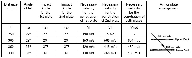
Lower penetration zone (40.6 cm armor-piercing shell, weight = 1,030 kg)
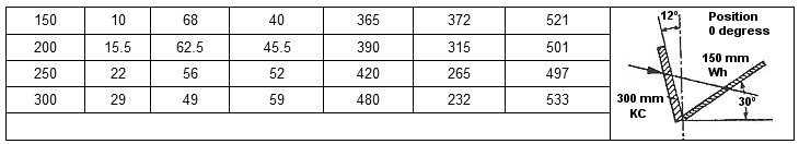
Fig. 11. Determination of limiting [critical] distance (Example).
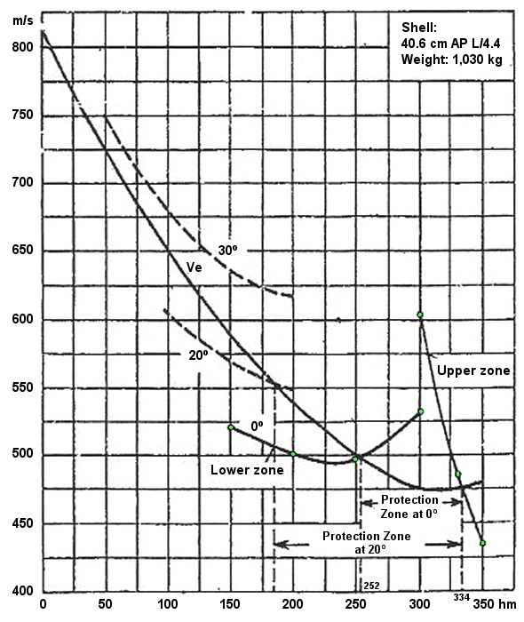
Fig. 12 Graphic determination of the limiting distance (both penetration zones).
Furthermore, this kind of graphic presentation is not only a good method to determine the limiting distances for a given combination of armor, but it gives a good overview of the general aspects regarding the effectiveness of an armor protection scheme. Please, allow me to give you another brief example. A basic analysis of the formation of the scarp triangle is shown in graph, Fig. 13, i.e., the optimal relationship of thickness between the armor belt and the scarp. The Vnot [velocity necessary for penetration] for a combination of 300 mm KC + 150 mm Wh lies lower than the Ve [velocity actually available] at a passable battle distance. Therefore, the combination [of plates] is still penetrated above 300 hm. A re-enforcement of the scarp by just 60 mm, however, tips the scale of the curve into the region of shorter distances so decisively upward that the Vnot curve for the combination of 300 KC + 210 Wh lies already above the Ve curve at all distances. In other words, a scarp triangle that consists of 300 mm KC and 210 mm Wh (below 30ş against the horizontal plane) is secure against any hit by a 40.6 cm armor-piercing projectile weighing 1,030 kg.
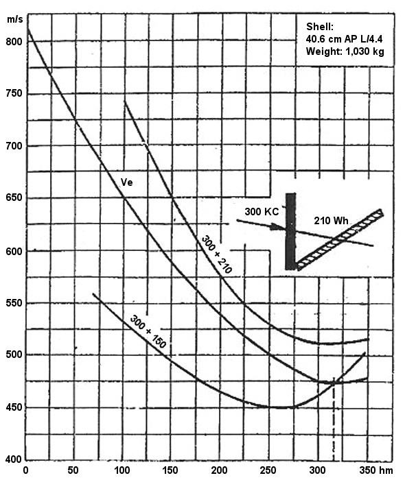
Fig. 13. Graphic determination of the limiting distance (optimal triangular scarp configuration).
Unfortunately, my time is up and I cannot give you further examples. Suffice it to say to you that these methods have been able to answer all questions that have arisen from practical experience.
Nevertheless, even the Navy tried, at least in their certain subsections, to replace empiricism with scientifically exact calculations. Various attempts were made, but during the war such scientific work had to be dropped completely because of shortages in personnel and time. However, this is justifiable, because the necessary documents [manuals] for answering any really practical questions are already at hand. Naturally, the intention to resume these scientific labors later is self-evident, probably after the war is over and when sufficient personnel are again available. It is hoped that even the numerous materials alluded to here, which are based on many years of comprehensive efforts and experimentation, will provide valuable assistance to the future scientific endeavors. The Navy will naturally be glad to provide these documents to other offices which are engaged in similar research.
Gercke: In support of the “empirical” penetration formulas that have been communicated in several lectures and whose deficiencies various speakers have pointed out, the following comment is made. Their great utility lies in the fact that they facilitate the establishment of penetration curves for a certain caliber’s test results and allow the additional extrapolation for the incorporation of other calibers and certain controls; namely, the more [data], the larger the scope of validity. Formulas that have a high degree of validity can be established, as in the case of the penetration tests by the Navy, when only one shell type and only few plate types are dealt with. Therefore, it was possible to summarize, in a single penetration formula, the entirety of armor firing tests that used 15 to 40.6 cm armor-piercing shells against homogenous as well as KC plates. Therefore, the complete data for the individual calibers could be combined in graphs as a single unified system, which now permits the incorporation and extrapolation of test results as characteristics for the development of penetration curves of other calibers for subsequent ballistic calculations, and, thus, provides a saving in firing tests.
With regard to the question of the calculations for armor penetration, basically two methods need to be differentiated. One way, starting with a simple physical concept of the penetration process, is to develop a computational procedure as Burkhardt has proposed; the aim of his end-result could state [penetration characteristics]: given a shell drawing and the material specifications of the shell and plate [it impacts]. Then, the calculation may perhaps investigate the marginal [critical] limit of the penetration velocity for various impact conditions as well as the influence of related variables, e.g., projectile shape. The alternate way of calculating armor penetration would start with the establishment of empirical formulas; if developing of relevant empirical expressions can be accomplished from purely mathematical interpolation formulas in which the physical behavior of the controlling parameters, such as material specifications or the projectile’s shape, appear to be very carefully considered. Then, the final goal cannot result in obtaining a generally applicable penetration formula, but at best a set of formulas, each of which is valid only for a certain shell and plate type.

| Home Guestbook Quiz Glossary Help us Weights & Measures Video Credits Links Contact |